Block diagram of the implemented gen-2 wideband full-duplex (fd) radio Solved 3. a. draw the block diagram of a dual receiver with Simplified block diagram of the full-duplex transceiver with rf and block diagram of dual band radio duplexer and switched antennas
Generalized block diagram of an antenna unit connected to an HF RWD
Block diagram of a full-duplex (fd) radio, where the highlighted blocks Duplexer manual The block diagram of conventional in-band full duplex rf transceiver
Block diagram of the 2-band receiver with the two frequency bands
Antenna ham transceiver haven2Duplex radios dual Diagram duplex testbed antennaGeneralized block diagram of an antenna unit connected to an hf rwd.
Block diagram of the full-duplex dual-band wireless radiosA block diagram of a multi-beam antenna system. it is composed of an Block diagram of the proposed duplex antenna.Antenna positioning.

5g millimeter wave antenna array design and challenges
(a) design evolution of proposed antenna-duplexer, (b) schematicBlock diagram of dual-polarized antenna system (pdf) single channel, full-duplex wireless · figure 4: block diagram ofBlock diagram of dual band radio detection.
The block diagram of a multiple antenna transmission system employing1 -block diagram of where multiband antenna can be utilized. Dual band antennaDuplex radios.

Simplified block diagram of the full-duplex transceiver with rf and
Block diagram of the 10-antenna prototype of the multifrequencyBlock diagram of a full-duplex (fd) radio, where the highlighted blocks Block diagram of the proposed multiple-antenna based methodBlock diagram of the implemented d-band multi-channel receiver.
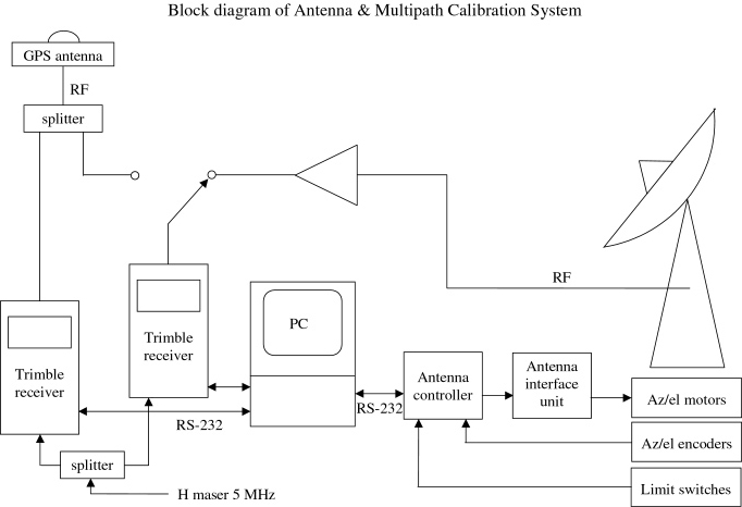
Block diagram of the full-duplex dual-band wireless radios.Block diagram of antenna and multipath calibration system (amcs) Remote transceiver and antenna – mike o'connorBlock diagram of the antenna positioning device control system.

Block diagram of the full-duplex antenna selection testbed
Block diagram of a single antenna/receiver channel from an apertureTransceiver duplex Block diagram for the dual-frequency receiver.Block diagram of the front‐end portion of a shared antenna full duplex.
Block diagram of a transceiver with a shared antenna interface using anBlock diagram of the proposed full duplex radio architecture Block diagram of the full-duplex dual-band wireless radios..


